


Member
Posted 24 December 2011 - 21:57
Advertisement

Member
Posted 25 December 2011 - 01:20
Member
Posted 25 December 2011 - 13:58
cheapracer,
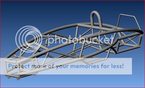
If you don't mind a bit of nitpicking, here's my two-cents on the pictures you posted of a tube chassis front end structure.
First, there is the basic issue of load paths and triangulation in tube truss structures. Ideally, for optimum structural efficiency, all of the tubes should be arranged to transfer loads purely in tension/compression. Having the upper A-arms attached to a tube mid-span puts that tube in bending. There is also an issue with the upper spring/dampener attachment, the structure behind it is not fully triangulated.
Second, I don't believe the upper A-arm structure is properly constrained, since there is a rotational joint located mid span in the front leg.
Third, while it's hard to tell from the pictures, it looks like there might be some bump steer in the steering linkage geometry, due to the location of the inner tie rod joints.
slider
Member
Posted 25 December 2011 - 14:22
Costin's remark that Lotus Mk 8 spaceframe* was nearly perfect example of spaceframe in terms of stiffness and lightness (and best up-to-date)... I understand it had stressed floorboard and skin panels,
Member
Posted 27 December 2011 - 23:24
You do understand it's not mine?
1/ There's no doubt that feeding loads into nodes where it can be distributed appropriately is the best way to go but there's also a case for loads that are fed into tubes that are appropriate for the load size. Yes that could be arranged better and yes I would do the whole lot differently - but I still like the concept of the top A-arm support as it is.
2/ This is very common to get caster and camber adjustment, very common and thousands of race cars use this setup. You may be missing that it is a triangular structure and can not move. http://www.speedwaym...ieds,29430.html
3/ Wouldn't have a clue, would need more than one POV and a little math to know and even then would still come down to physical testing.


Member
Posted 28 December 2011 - 11:33
cheapracer,
Bump steer with double A-arm suspension:
regards,
slider
Edited by carlt, 28 December 2011 - 14:42.

Member
Posted 28 December 2011 - 13:39
I assume the reason to hang the top wishbones 'out on a limb', so to speak , is to attain a required ratio between top and bottom wishbones for a prerequired degree of camber gain etc
So why not keep the top and bottom wishbone length ratio the same , but lengthen them both so that the top wishbone is attached to the top chassis rail and the lower wishbone attached towards the centre line of the chassis bottom
Member
Posted 28 December 2011 - 14:38
the upper A-arm in your pictures is not properly constrained and has excessive kinematic degrees-of-freedom, due to the presence of a spherical joint at the outboard end of the tie rod.

Member
Posted 03 January 2012 - 13:12
It may well have been at the time but of course these days after many years of development and FEA it looks a little lacking in some areas especially the open top of the engine box amongst others.
Stress skinning is not as good as bracing - of course a stress skinned tube (aeroplane, cigar racing car etc) is a different thing again.
 ).
).
Advertisement
Member
Posted 03 January 2012 - 13:42
Recently, I've stumbled on a small (and free!) program which I find ever more appropriate- it does a 'classical' analysis of a frame, calculating the tube loads and taking into account buckling... I don't think it works with gussets, but once the tubes needing them are identified by it it's rather elementary to see whether the problem can ber aliviated by using them.

Member
Posted 03 January 2012 - 18:20
Member
Posted 03 January 2012 - 19:42
Edited by Wolf, 03 January 2012 - 19:43.

Member
Posted 03 January 2012 - 20:07
Classical linear FEA takes no account of softening due to applied moments etc, or buckling. I'd be a bit surprised if a car's spaceframe was operating at high enough stresses for this to matter, and still be worried about stiffness. Still, it is nice to see spaceframe analysis improving, thanks for the linky. Maybe somebody could dig up a non linear FEA of a spaceframe, or even (shock horror) a physical test showing this.
here's an FSAE report, linear range only sadly. Swinburne have got FSAE-A reporting down to a fine art:
http://users.telenet.....E Chassis.pdf
But I know my customers would not believe an FEA model that was 150% stiffer than test.
Here's a non linear FEA of spaceframes, nice and curvy, but no test results
http://kuiraq.com/li.....they maky.pdf
Yeah, bridgebuilder aka pontifex was surprisingly popular for a while. the 2d one is freeware now.

Member
Posted 03 January 2012 - 23:22
Member
Posted 04 January 2012 - 06:31
Blimey! Without knowing the severity of the impact it's hard to tell whether that is a good result or a horrendous one - it looks worse than it might, I suppose, as several tubes have been chopped out by the rescue team.
Member
Posted 04 January 2012 - 11:12
I'm slightly ashamed to admit that I was refering to the chassis and not the driver...Broken legs to the driver I believe but otherwise ok.

Member
Posted 04 January 2012 - 11:36
I'm slightly ashamed to admit that I was refering to the chassis and not the driver...
Member
Posted 04 January 2012 - 12:17
I think it is surprising that anyone survived this accident at all - it must say something for the progressive crumpling of the chassis tubes.
Member
Posted 04 January 2012 - 14:16
Member
Posted 04 January 2012 - 14:49
I don't see how you can say that without knowing the force involved. If it was a 15 mph collision it doesn't look too good, but if it was 70 mph...
Member
Posted 04 January 2012 - 20:34
It was reputed to be 100 mph, I avoided saying it as I don't believe it for a moment.
Those are 4 x 50mm tubes well braced and check out the front suspension box up there as well, so that kind of compression and damage does point towards a very hefty impact.
Member
Posted 05 January 2012 - 02:15
It was reputed to be 100 mph, I avoided saying it as I don't believe it for a moment.
Those are 4 x 50mm tubes well braced and check out the front suspension box up there as well, so that kind of compression and damage does point towards a very hefty impact.
Member
Posted 05 January 2012 - 05:16
This is the first time I have seen a clear picture of the Atom chassis (I presume that it is an Atom). Why are those bottom main frame members curved? It would seem to me that making them straight and at the bottom of the chassis would be a better and simpler idea.
I get the impression that they are curved just to make the car look distinctive. Maybe FEA says that curved is better? (Sad attempt at humour).
For that matter - why are the top rails curved? - there would seem to be no advantage in this.
Member
Posted 05 January 2012 - 06:18
I don't see how you can say that without knowing the force involved. If it was a 15 mph collision it doesn't look too good, but if it was 70 mph...

Member
Posted 05 January 2012 - 08:04
This is the first time I have seen a clear picture of the Atom chassis (I presume that it is an Atom). Why are those bottom main frame members curved? It would seem to me that making them straight and at the bottom of the chassis would be a better and simpler idea.
I get the impression that they are curved just to make the car look distinctive. Maybe FEA says that curved is better? (Sad attempt at humour).
For that matter - why are the top rails curved? - there would seem to be no advantage in this.

Member
Posted 05 January 2012 - 09:20
Member
Posted 05 January 2012 - 10:55
curved tubes are a design feature... Truth be told, this whole car, as much as I like it, has been mostly designed then engineered.. The floor section is a joke IMHO, but it does look good..
Member
Posted 05 January 2012 - 17:11
Member
Posted 05 January 2012 - 19:08
Well in that case I reckon the chassis did a pretty good job. However, I think a chassis, in fact any sub-assembly or part should look good enough to hang on a wall or put in a display cabinet. The Atom chassis on its own is, in my opinion, aesthetically grim, however tough.The owner had accelerated flat through the first 3 gears and was approaching the 'T' intersection at 90 to 100mph. When he lifted the engine didn't, jammed throttle and he applied the brakes but only the fronts locked with the engine overpowering the rears and straight into the wall they went.
Advertisement

Member
Posted 05 January 2012 - 20:26
The Atom crash we were talking about above happened in Belgium and a Belgium Journo has just been killed in one and the driver's not too good apparently...
http://jalopnik.com/...est-drive-crash
Member
Posted 05 January 2012 - 21:56
Member
Posted 06 January 2012 - 04:29
I don't want to sound unsympathetic - I'm not - but modern performance cars and especially bikes are just way too quick to use at anything near their full potential on public roads.
Member
Posted 06 January 2012 - 04:52
Yup, we had recent discussions about bikes and I believe there is no place for Hyperbikes anywhere.
I was blown away by Greg recently when he said "We don't make a family car that does less than 150mph" - it's just gotten insane.
Kiki, never liked the Seven's lack of protection ..
 I was surprised to hear Isignosis' quote when asked on safety of Mini- something like "I've given them good power, good brakes and good handling- if they get into accient anyway, it's their own fault" (another of his classics is "I make cars to be driven, not to be wrecked", or something to that effect)..., but I don't think you'd be unkind to the design*)
Edited by Wolf, 06 January 2012 - 04:54.
Member
Posted 06 January 2012 - 05:11
* it will be GPL suicide pod- 2 seater with basic Lotus 25 layout in GRP
Member
Posted 06 January 2012 - 05:17
What's a Hyperbike???
Member
Posted 06 January 2012 - 05:22
Sounds interesting - have you got a sketch or drawing you can post? What's a "suicide pod"?

Member
Posted 06 January 2012 - 06:35
Member
Posted 08 January 2012 - 14:12
Lack of protection on 7, Cheapy?
Member
Posted 08 January 2012 - 15:08


© MOTORSPORT NETWORK 2024. All rights reserved. Community Forum Software by IP.Board
